A couple of months ago I did a strong effort towards automating build-related tasks of our iOS app at Base (you can read more on that in my previous blog post). The result was amazing, especially when it comes to preparing AppStore submissions, that normally require much more effort than just doing a release build. Our team really enjoyed the new tools:
[caption id="attachment_452" align="alignnone" width="1024"]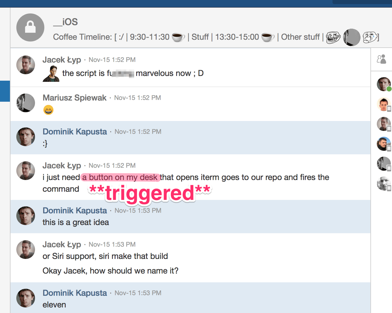 https://www.youtube.com/watch?v=NMS2VnDveP8[/caption]
Siri support aside, the button instantly caught my attention. It sounded like a simple project with (somewhat) real-life use case. My friend was in need and I could help him out, possibly sparking his and our other colleagues' interest in learning more about embedded programming. And, after all, you always wanted a big button on your desk for whatever purpose, admit it.
Scope
I defined the following requirements straight off:
- The button would connect to the computer and run a predefined command. Fastlane runs in terminal so I assumed it would first open a system shell and then execute the command.
- The wired connection is so 2000, the Wi-Fi connection is too much and not really handy ⇒ Bluetooth Low Energy sounds just fine. I know close to nothing about it (barring mobile apps working with BLE beacons), but that's fine since I'm going to learn it.
- I could write a client app on the OS X that would connect to the button, and allow for configuring its action. I'm normally doing roughly one OS X app every 4 years and it was about time.
Hardware
Remember I said I knew nothing about Bluetooth? That's true to the extent that I wasn't sure whether I'd achieve what I wanted with Bluetooth Low Energy, or I needed to go with Bluetooth Classic. I also wanted to cut costs a little bit, so I decided to give it a try with ESP-WROOM-32 microcontroller from Espressif Systems. It's a very powerful dual-core chip with WiFi, BLE, and Bluetooth Classic connectivity, and it measures a mere 18x25.5mm with integrated PCB antenna included.
[caption id="attachment_454" align="aligncenter" width="1532"]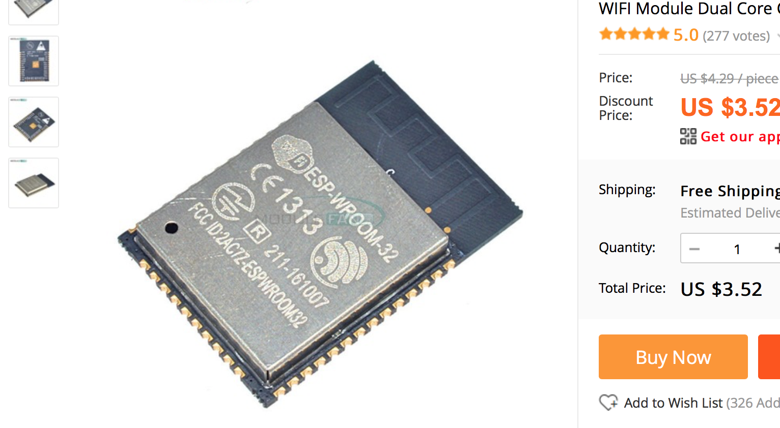 Cutting costs pretty aggressively actually.[/caption]
It has a 1.27mm raster which meant some serious SMD effort just to connect wires to it, so I ordered two chips in case I fail, and planned to solder it to the ESP-32-specific 2.54mm raster adapter.
Fun
For the most crucial part of the device, the Adafruit Massive Arcade Button was the obvious ideal candidate. It features a 10cm diameter dome with an LED backlight, and since I saw it for the first time I was looking for a good enough excuse to finally get it.
Ready, set, go!
One month later when the package from Singapore arrived, I was ready to get my hands dirty. It was a very wise decision to order two chips, as it didn't take long till I failed at putting the first one on the adapter. I didn't notice the slight misalignment in the left upper area and made several short circuits, and then unsoldering the chip using decent temperature was too much for my skills.
[caption id="attachment_455" align="aligncenter" width="1024"]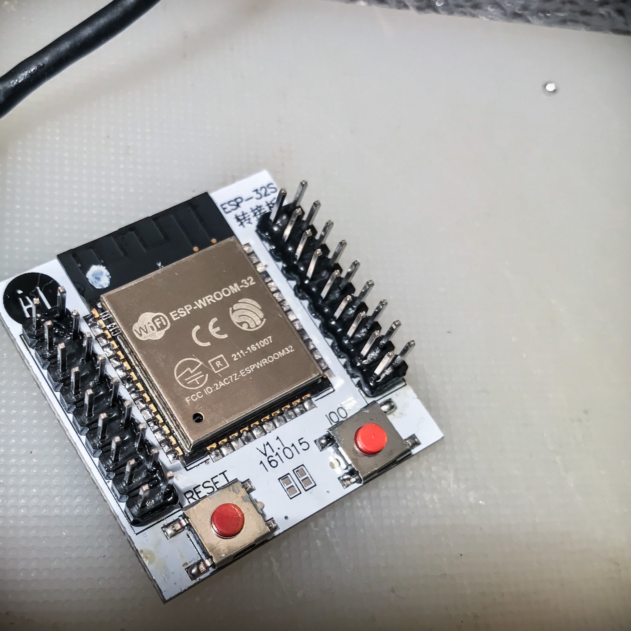 How to: waste your shiny new ESP-WROOM-32 by soldering it misaligned.[/caption]
If that was not enough of a bad luck, I wasted the other chip in a similar way just a few moments later. (I thought) I soldered it properly this time (without obviously visible misalignments), but still, something went wrong, as I lost the connection to the chip soon after I powered it up.
Step back. Regroup.
Having failed so miserably I resorted to getting a dedicated development board. I thought I'd do it the right way – start off with the dev board, and having figured out the working prototype, I'd replace it with a bare microcontroller and only the required circuitry. Luckily enough I got an ESP-DevKitC just before the Christmas break.
Prototype
The circuit is really simple – here's what's needed:
- 1x ESP-32 dev board,
- 1x tact switch,
- 1x LED,
- 1x resistor (to limit the LED current).
The LED (and the resistor) could be omitted but since it's already provided with the Adafruit dome button, let's make some use of it.
[caption id="attachment_456" align="aligncenter" width="2560"]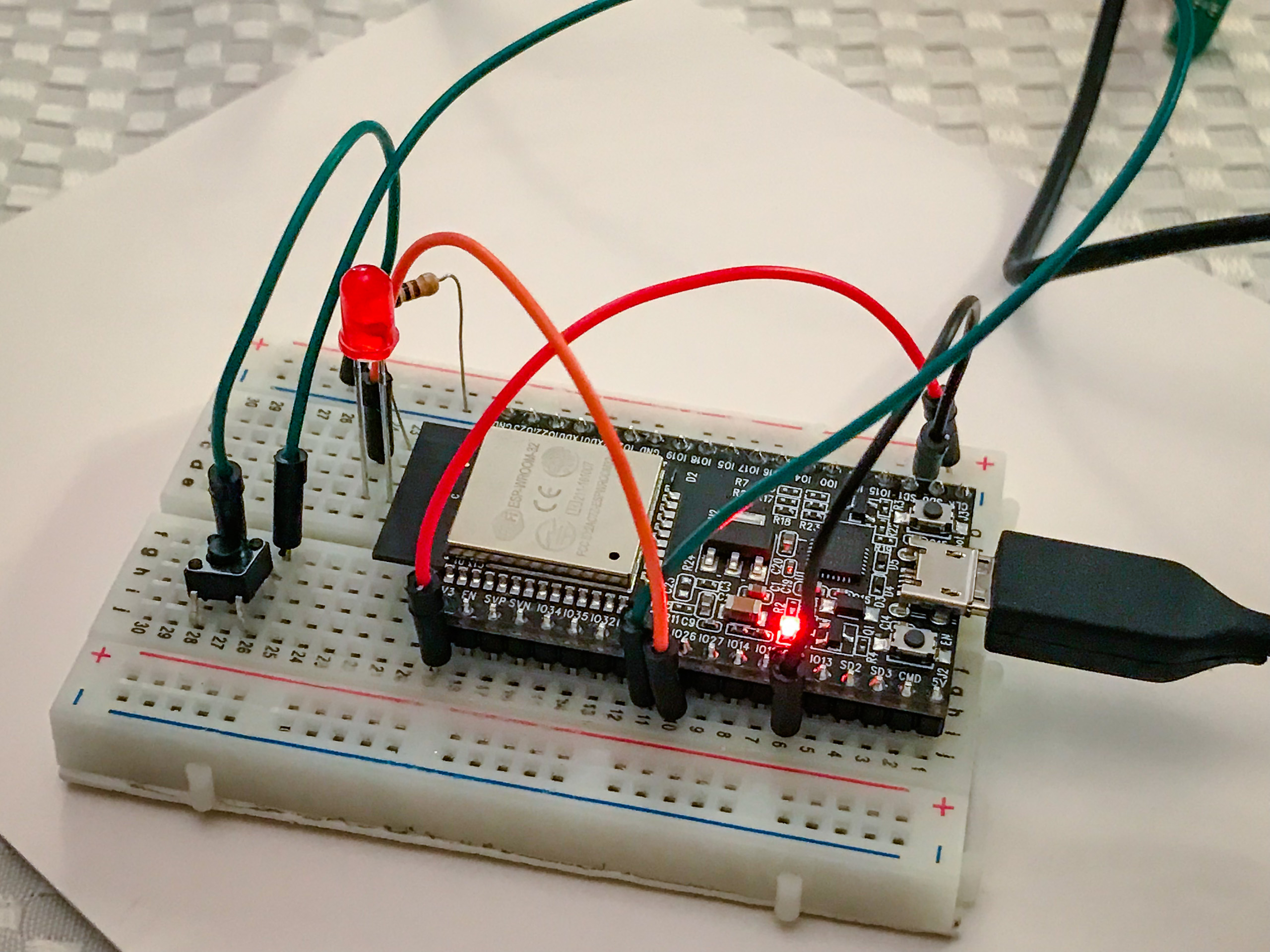 Simple as that.[/caption]
Working principle
I imagined the big picture the following way:
- the button device is a BLE accessory, just like a heart rate monitor,
- the computer is a client that connects to the button; it can be configured to run a predefined command when triggered,
- when the button is pressed, it notifies the client; it also switches on the LED to indicate a busy state,
- the client acknowledges the notification and runs a command,
- when the command finishes, the client updates the button so that it turns off the LED and waits to be pressed again.
First run
Like I mentioned earlier, I was new to Bluetooth Low Energy, especially server-side, and then I was also new to ESP-32 and esp-idf development environment. Having spent some quality time coding in MicroPython for Pycom boards, I was pretty upset to realize that at the moment ESP-32 MicroPython still lacks some of the chip's features, including Bluetooth APIs. This meant that I had to resort to plain C programming in FreeRTOS environment.
Fortunately, I was able to base my work on the GATT Server example of the esp-idf, and adjust it to my needs, removing unnecessary code and adding handlers for the button and the LED.
After some trial-and-error fiddling with both the development board and the OS X app I was extremely happy to see them interact with each other:
[vimeo 251331227 w=640 h=360]
Implementation
Server (the button)
Going into details, the button implements the GATT Server, and the computer acts as a GATT client. The Server defines two services:
- trigger – with the read-only characteristic with notification capability, sent out when pressing the button,
- idle – with write-only characteristic, accepting a boolean value (effectively only the
truevalue) to indicate that the task finished.
Client (the computer)
The Client searches for peripherals with mentioned services. Once found and connected, it sets the idle characteristic to true and requests notifications for the trigger characteristic. In the UI it allows for defining a command (or set of commands) to be passed to the Terminal.app for execution.
[caption id="attachment_460" align="aligncenter" width="398"]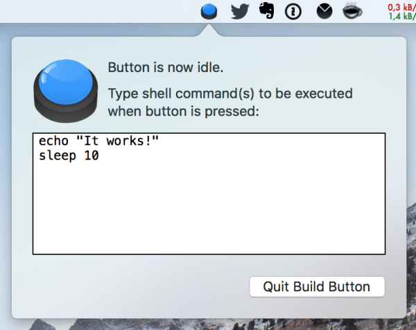 So much for the UI.[/caption]
Now for the tricky part: figuring out when the command finished. Since the app passes control to the external application (Terminal.app), to know when Terminal.app is done running a command, it needs to handle some kind of inter-process communication. Which is not a big deal, at least compared to how to tell the other app to notify my app back.
Inter-process communication in MacOS X
Well, in case of Terminal.app, it runs a system shell so we can easily inject some command into the shell to do a callback for the BuildButton.app. As it comes to the IPC itself, there are several solutions for OS X ranging from a shared file on disk to using Mach ports. I ended up somewhere in between by using the oldie but goodie Apple Script. With its funny, naïve syntax and the ability to expose virtually any behaviour to the app's scripting interface I believed it was the right tool for the job here.
For opening up the Terminal and running a command, I came up with the following helper script:
on runInTerminal(command)
    tell application "Terminal"
      activate
      set newTab to do script(command)
    end tell
    return newTab
end runInTerminal
And the command itself had to contain the actual user-defined list of commands, plus a callback to our app:
let argument = { () -> String in
    let finishCommand = "osascript -e 'tell application \\\"BuildButton\\\" to finish'"
    if commandToRun.isEmpty {
        return finishCommand
    }
    // commandToRun is the user-defined command
    return "\(commandToRun); \(finishCommand)"
}()
What does it mean to tell application "BuildButton" to finish? Have a look at the definition:
<command name="finish" code="bbfinish" description="Finish current task.">
    <cocoa class="BuildButton.FinishCommand">
</command>
It tells the app to use FinishCommand, which is a subclass of NSScriptCommand and does the actual job of updating the idle characteristic of the button.
The dedicated button circuit
 Since the dev board prototype turned out working fine, I could finally order THE BUTTON, and design a PCB for the circuit. I also decided to give it a last shot with soldering the bare ESP-32 chip to the adapter and I finally got it right :D
The first version of a circuit contains the following components:
- 3xAAA battery power supply (4.5V),
- 3.3V step-up/step-down voltage regulator for the ESP-32,
- 9V step-up voltage regulator for the LED (I was told it's for 5-12V but I was short of time and I didn't want to risk it not working or flashing too dim),
- an additional circuitry for the chip to work fine: power supply capacitors, and EN and IO0 pin pull-up resistors,
- button interface,
- LED interface,
- programming interface (UART + VCC/GND).
This is the schematic:
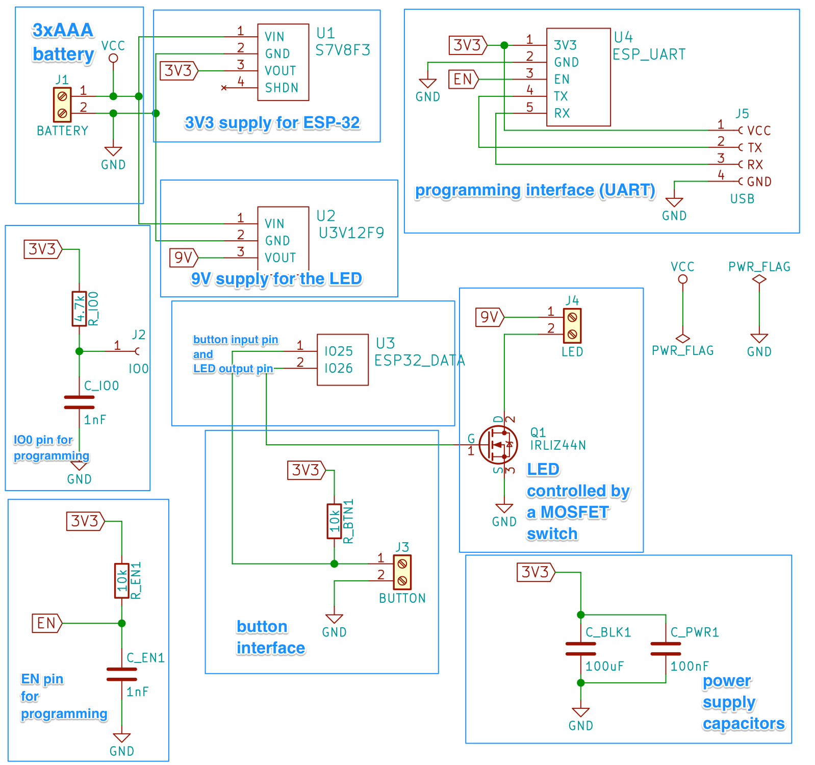
I copied over some part of it (like EN/IO0 and power supply capacitors) directly from the schematic of ESP-DevKitC which is available online. If you take a closer look at my schematic, you'll notice that it's highly unoptimized, e.g. it includes two DC voltage regulator circuits: a step-up 9V for the LED and a step-up/step-down 3.3V for the chip. Firstly, it's a pretty expensive solution, and also the 9V regulator drains about 1mA of constant current when idle, with significant impact on battery life.
Power supply issues
I did some initial bare board testing with the circuit similar to this:
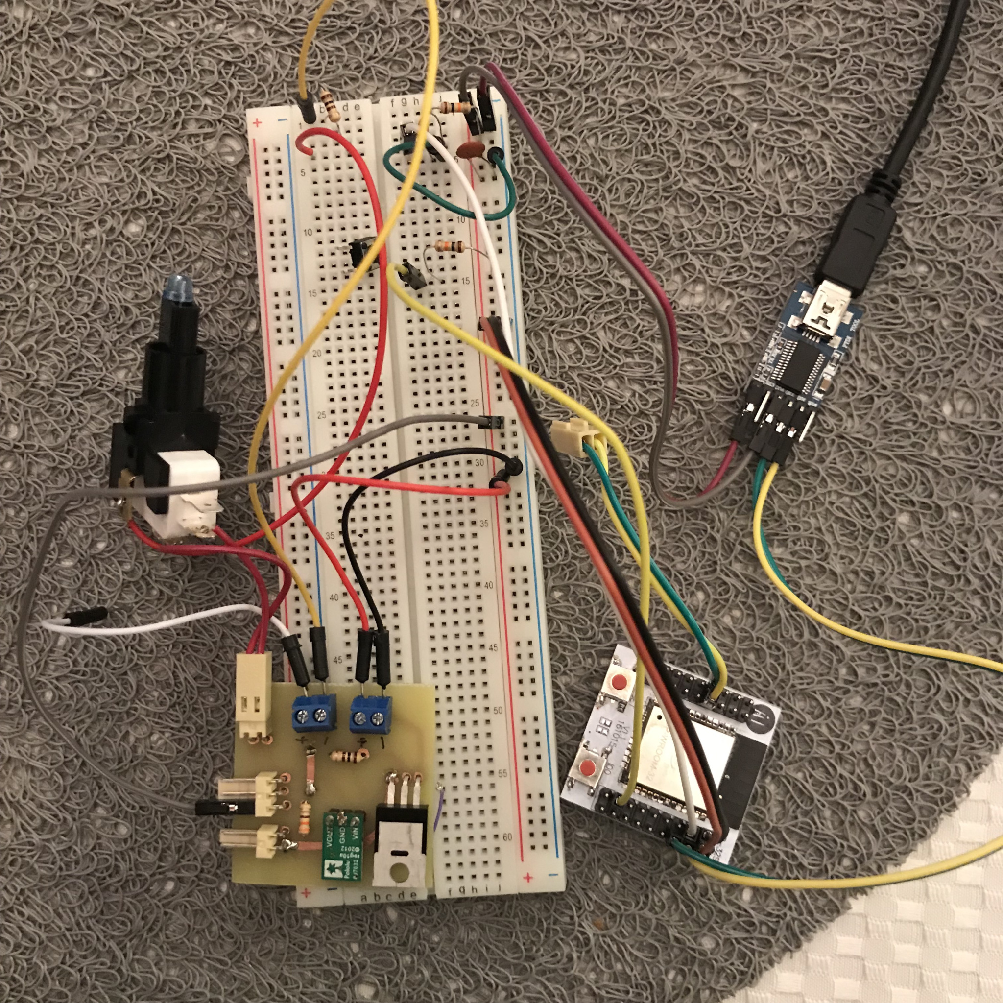
And I couldn't get it to work because the chip was constantly restarting right after booting up. The console output showed the following message:
Brownout detector was triggered
It means that the power supply can't deliver high enough voltage to drive the microcontroller. In my case, I was powering it from my computer's USB port via the USB-UART adapter, which should deliver a solid 3.3V for up to at least around 500mA. I also tried the same with a 3.7V Li-ion battery and the standalone regulated DC adapter with no luck. Then I decided to have a look at the program I was running on the ESP.
When I tried it with a simple hello world example, everything worked fine. But every time I initialized Bluetooth, the brownout detector fired and restarted the device. This must have been caused by a high current peak occurring when powering up Bluetooth. And that's what the bulk capacitor sitting between power supply lines is supposed to handle – cover the current peaks with its charge. In my case, however, it didn't work with a capacitor placed on the breadboard. When I later dug into the topic I learned that this capacitor:
- should be added as close to the chip power input as possible – apparently, a 20cm wire between the breadboard and the microcontroller is not close enough,
- should be of high quality, i.e. low impedance – the regular electrolytic capacitor is actually quite the opposite.
Even trying to place the huge (680uF) electrolytic capacitor so close that it directly touched the power input pins didn't work. I ended up disabling the brownout detector in my chip, which is obviously not recommended*, but it didn't cause any unexpected crashes in my case. I still ordered a bunch of low ESR SMD capacitors and hoped it would work on the final PCB.
[*] - you usually risk the undefined behaviour in places where the logic level cannot be determined due to the voltage being too low for a logic one, yet too high for a logic zero
Printed board design
For the PCB, I wanted it to be some kind of a "hat" on top of the ESP adapter board:
[caption id="attachment_466" align="alignnone" width="1024"]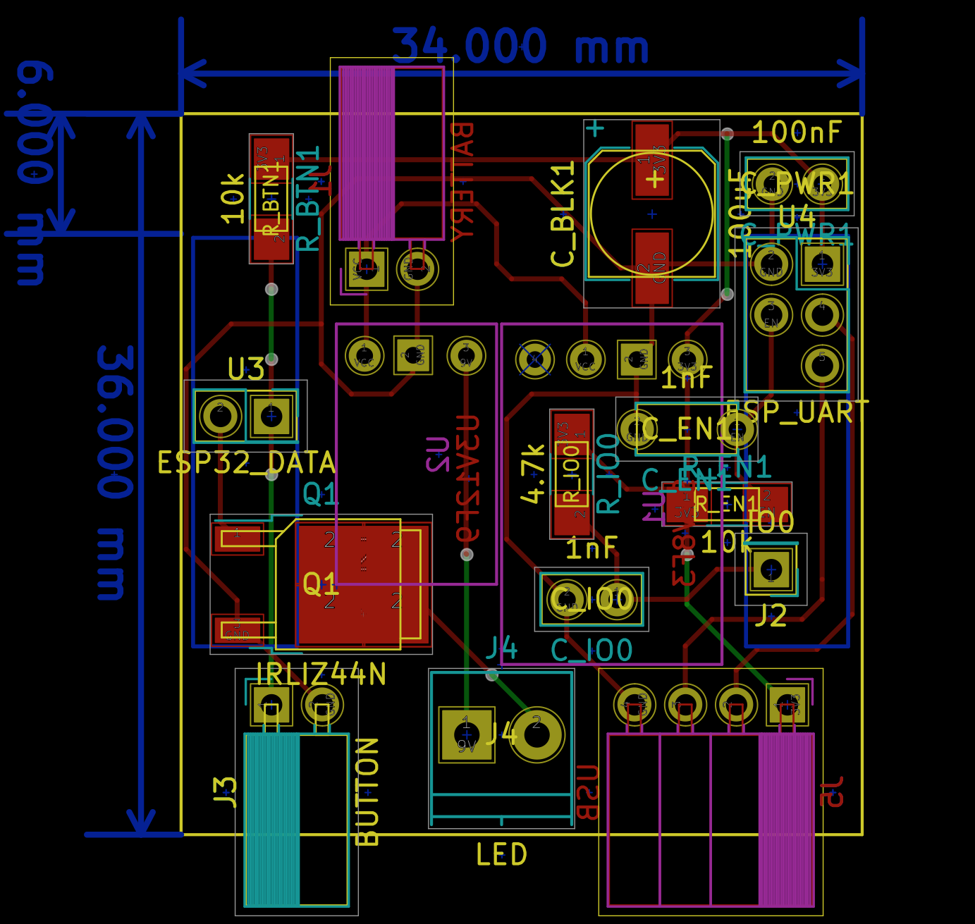 Quite a tight fit for a hand-made PCB, if you ask me.[/caption]
Even though the dome button itself is huge and it needs an even bigger case, I went with a reasonably small form factor, and the final board looked like this:
[gallery ids="470,468,469" type="rectangular" link="file"]
With help of some velcro and a glue gun I managed to put everything in a box:
[gallery ids="472,473" type="rectangular"]
And give it a proper test:
[vimeo 251343761 w=640 h=360]
Also, with the bulk capacitor soldered just millimeters away from the VCC/GND pins I managed to get rid of the brownout issues!
Recap
I must say that when I thought of doing the button for the first time, I had no idea just how much work it would require. After all, it sounds extremely simple, you press a button and it does one simple thing on the Mac. Obviously the requirement of using plain C language for the ESP32 app had huge impact on my perceived effort of this project. And while the device does its job already and I can showcase it to people and get very positive feedback (again, who doesn't like big arcade-style push buttons), it's not yet ready to be left alone in the office for the guys to actually trigger builds with it.
Have a look at the short list of features:
- it can connect to the client app and remember it
- it, most importantly, can trigger a client app to run a command
- it does the pulse/heartbeat LED flashing when the command is run; the heartbeat stops when done, or it can be turned off by pressing the button again while running the command (it effectively resets the button state to idle)
- it goes to deep sleep after 20s of inactivity (very short time, to conserve battery); when pressed during deep sleep it starts advertising and if the remembered client connects to it, it sends trigger notification - but this adds a 2-3s delay.
And for bugs, or stuff that's missing:
- The device drains around 1500uA when sleeping, and I bet it's due to the sophisticated voltage regulators I used for both the chip and the LED circuit. Skipping these regulators should have reduced the deep sleep battery drain, and I'm going to give it a try.
- The ESP-32 drains up to 150mA when Bluetooth is active and LED is flashing and it's a ridiculously high current. I tried optimizing it by e.g. clocking down the CPU, disabling one of the cores, limiting Bluetooth radio power but no luck so far. I don't use WiFi when the chip is running, and the LED current is less than 10mA. It may be that ESP-32 is simply not the right tool for this job. The Nordic Semiconductor's nRF51822 would probably work much longer, but would possibly require even more work (...?)
- Switching between clients is not sorted out yet – for now it needs the currently paired client app to disconnect (e.g. by quitting the app) in order to connect to the other one. I wanted as minimal UI as possible in the device, so I ended up with just one button. I recently implemented the long press recognizer and I'll try to add pairing mode there.
And so on and so on... Even if the project is unfinished, it gave me yet another solid lesson of embedded systems. I was able to learn about esp-idf, basics of Bluetooth Low Energy, soldering 1.27mm raster integrated circuits just to name a few. Oh and AppleScript, obviously :)
Also, you know it was worth the effort, when people want to have such a button right after you showcase it to them. And when you give an awesome talk on improving iOS apps build performance and automating tasks, but the main topic on Q&A is how does the button work?:
https://www.facebook.com/lodzwiosluje/videos/1221621174637929/
I'll still be tinkering with the button as time permits, trying to make something shippable. The up-to-date code is available on GitHub, for both the button itself and the client app. Stay tuned for more weird stuff!