It's been a while since I deployed the air quality monitor on my balcony. If you're reading this, chances are you have seen the first article where I described the lengthy process of getting it to work with the ESP32-based WiPy board, optimizing battery usage, visualizing the data and putting everything in a box. Over 2 months later I'm after several iterations of improving it, fixing issues and trying out new solutions.
To recap, the first release version had the following features:
- Measured values:
- PM2.5 and PM10 concentration via a PMS5003 air quality sensor,
- temperature and relative humidity via a SHT10 sensor,
- battery voltage using the Pycom expansion board's built-in voltage divider and ESP32 analogue-to-digital converter,
- total measurement duration.
- Measurements were taken roughly every 10 minutes (controlled by a not-so-accurate built-in ESP32 real-time clock), they were sent over Wi-Fi to InfluxDB running on RaspberryPi in 6-datapoint batches (i.e. approx. every hour).
- Data was visualized in Grafana (also running on the RPi).
Battery wars continued
The 700mAh battery that I tested while publishing the previous article eventually lasted just over 5 days and nights, around 130 hours. I'd call it quite an impressive result, given that for every measurement the particulate matter sensor had to run for ~11 seconds, draining up to 200mA current alone. So the device stopped working because the battery couldn't supply it with a decent voltage anymore, and unfortunately, I found that the battery was completely dead and showing zero voltage.
PCM my ass
This is unexpected and somewhat disappointing, because the battery had the Protection Circuit Module (PCM) and yes, it was mounted there as I could see it, yet it apparently didn't do the job of protecting the cell from over-discharging. Also, judging from the battery voltage graph, definitely something went wrong in the last couple of hours, but I wouldn't say such weird behaviour can occur around 3.7V:
[caption id="attachment_486" align="alignnone" width="2836"]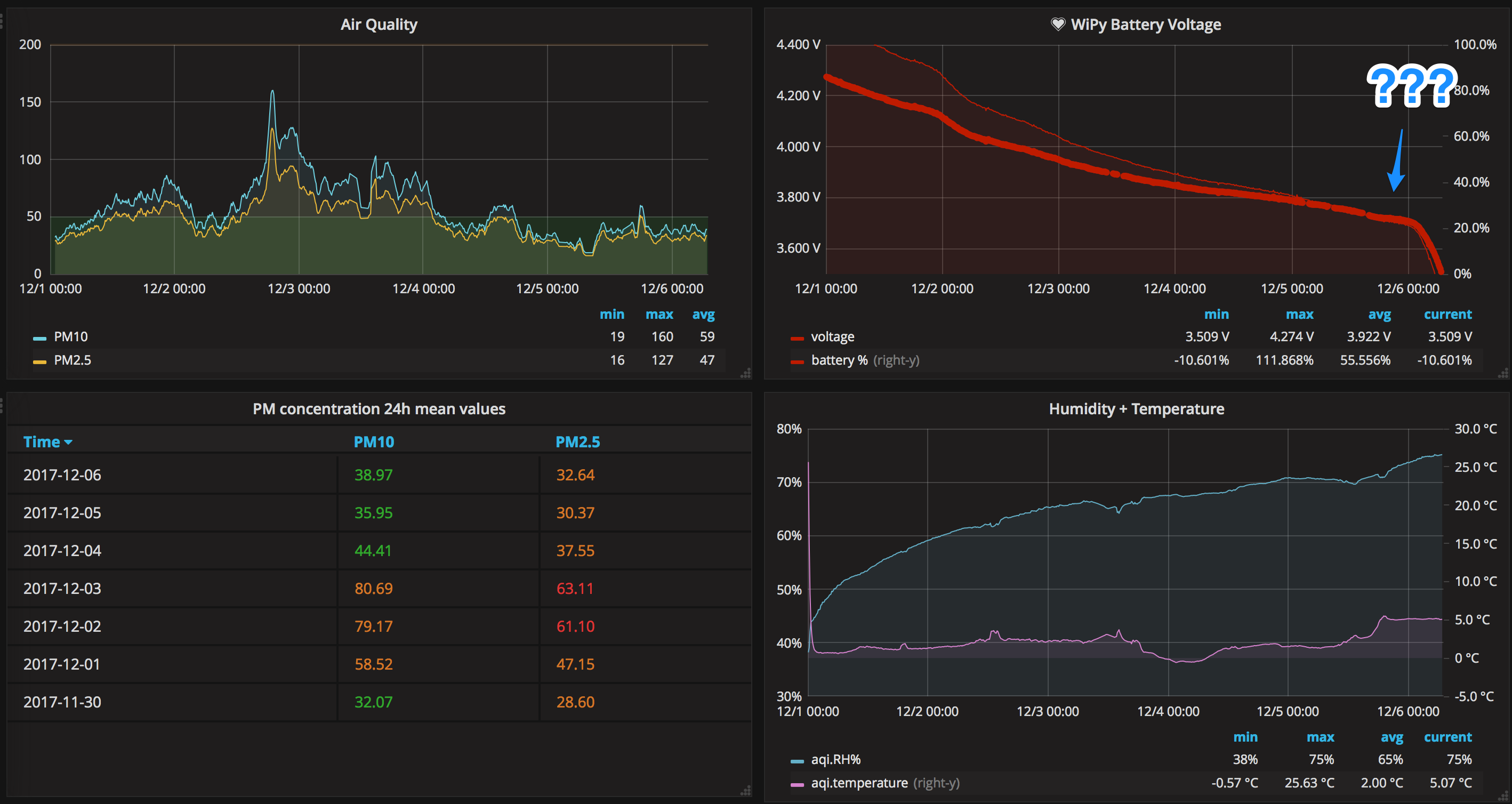 Other graphs attached as a proof that the system worked fine all the time during the heavy battery drain...[/caption]
The dead battery shows 0V on a voltmeter, and that's because the PCM is now apparently active and prevents it from powering the load. The voltage measured on the PCM module input showed 2.85V, which is far below a healthy 3.7-3.6V and even below the (deadly for Li-Po cells) 3.0V level.
The Big Boy
Not thinking too much about it I went on and replace the battery, this time adding a huge 2400mAh battery in hope that it would survive around 2 weeks on a single charge. In fact, it worked great for over 2 weeks, when on the day 16, at slightly over 3.8V, the device stopped working:
[caption id="attachment_media-40" align="alignnone" width="2856"]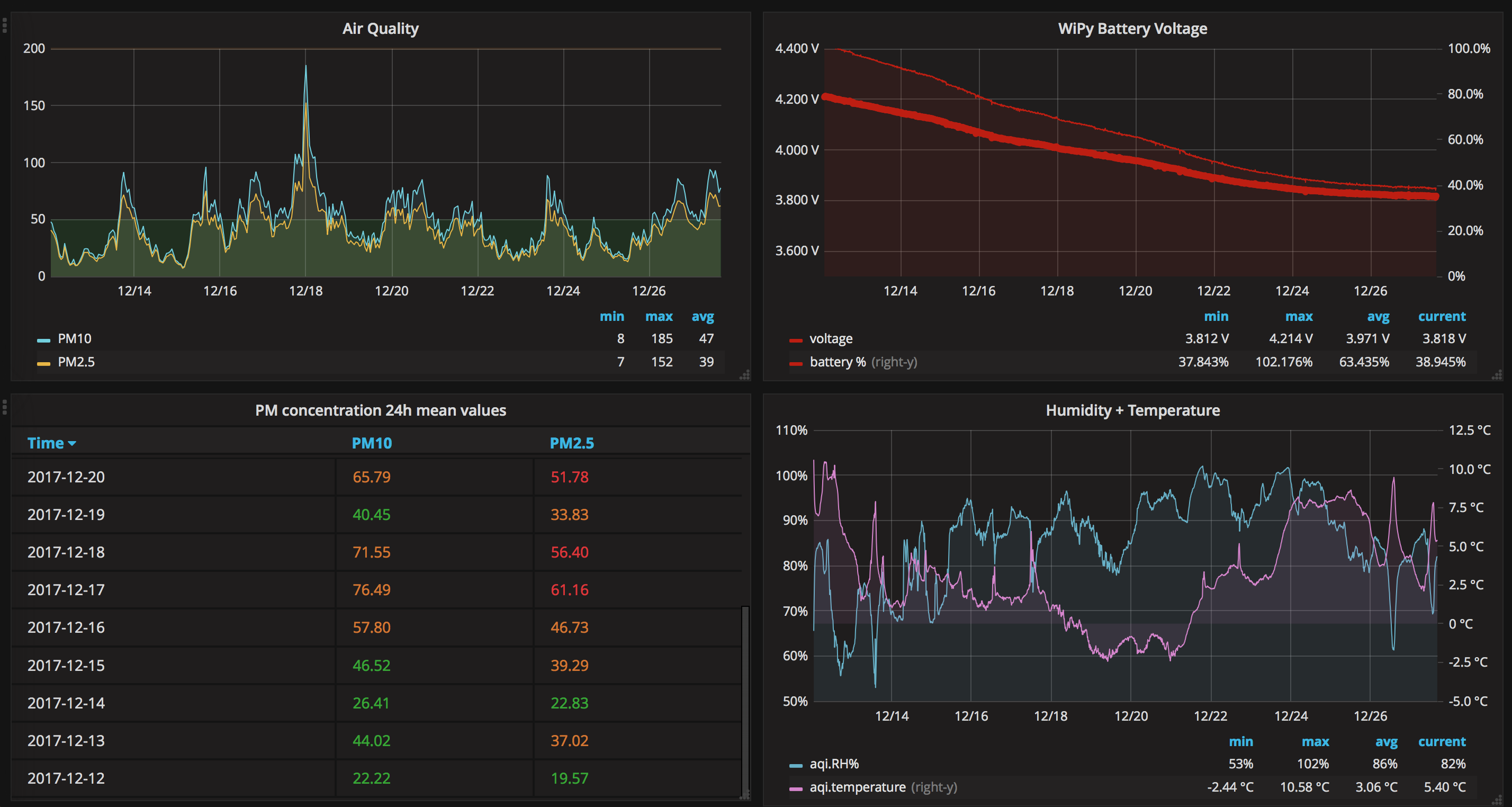 On the bright side, this means >2 weeks of uninterrupted uptime, yay![/caption]
At first, I was like "oh ok, the Raspberry Pi Grafana server went offline". But no, it didn't. The battery was dead again. With the same symptoms (0V and <3V at the PCM input). This was enough of a motivation to revisit the battery voltage measurement code.
It turned out that with some of the recent firmware updates that I got in the meantime, the attenuation level that I used for the ADC changed from 3dB to 2.5dB. This basically means that all the measurements were higher than the actual battery voltage, so when the graph said it was at 3.8V, it was in fact somewhere lower.
Confession
Ok, fair enough, but why the script didn't fail at battery voltage measurement function since ADC.ATTN_3DB changed to ADC.ATTN_2_5DB?
Because I used the raw value of 1, instead of specifying the constant:
# good
apin = adc.channel(attn=ADC.ATTN_2_5DB, pin='P16')

# baaaad!
apin = adc.channel(attn=1, pin='P16')
In previous firmware the 1 used to mean 3dB, and now it became 2.5dB. It wasn't my code after all, as I copied the code from elsewhere, but still, I didn't bother to carefully read it through and try to understand what's going on there and this is purely my fault. This is the great example of how not paying enough attention to your code can sometimes cost you real money.
All things considered, if the 2400mAh battery died after 16 days, given the discharging curve similar to that of 700mAh battery, we can safely assume that it would still be in a good condition after 14 days, which is the number I was hoping to achieve when planning the battery consumption for the system. Recharging the device twice a month is still not optimal, but quite acceptable for a home sensor.
MQTT
Mostly to just learn what it is and how it works, I wanted to test out the MQTT (Message Queuing Telemetry Transport) protocol. I went with ThingSpeak IoT platform by MathWorks. Setting up an MQTT channel is a no-brainer task, as well as sending the actual data when you have a dedicated library for that.
The air quality monitor, however, since it mostly just sleeps and becomes active only for a few seconds from time to time, is not the best application for MQTT. As a publish-subscribe-based protocol, MQTT can set up a connection once and keep it alive as the device transmits or receives data. Conversely, the HTTP sends one request per connection and then requires reconnecting for another chunk of data – this way it can drain the battery more than MQTT.
LoPy4
Back in November 2017, I preordered two LoPy4 boards, with LoRa and Sigfox connectivity (in addition to Wi-Fi and Bluetooth), 4MB RAM and 8MB flash memory 😮. The main purpose was to play with LoRa, and the natural first step – to connect the air quality monitor to LoRaWAN. When I received the boards a couple of weeks ago I started off by replacing the WiPy with LoPy4 in the device. Which turned out tougher than I would expect.
Running short of GPIOs
Both LoPy4 and WiPy (and all the other Pycom development boards) have the same amount of pins, but some of them are reserved, especially on more sophisticated boards. In case of LoPy4 (and the first version of LoPy), there are three pins reserved for communication with the LoRa chip. This way they can't be used by the developer. Add to that 6 input-only pins, 2 programming pins, a Wi-Fi antenna-switch pin and overall 9 pins taken by my device's sensors, it's getting pretty tight. If I were to add another peripheral, I might have a hard time finding a place for it.
Firmware and RTC issues
Like Pycom staff said on their forum, they got the boards a bit earlier than expected so they started shipping them while still ironing out the software. I could precisely feel it while watching my Guru Meditation errors in the console :) according to other comments on the forum, these errors could have been caused by importing some modules or calling specific functions/classes (e.g. machine.PWM in my case) too early in the main.py script. It was clearly a firmware bug and it seems to have been fixed in 1.14.0.b1 release.
The other thing I noticed in the LoPy4 was that the real-time clock didn't persist its state in deep sleep while on battery power. It worked perfectly fine (for an ESP32 RTC ;)) when powered via USB. This was something I heavily relied on, as the script's workflow looked like this:
- sync RTC with NTP server on first boot,
- take 6 measurements every 10 minutes,
- after 1 hour send the data via Wi-Fi and resync the RTC,
- repeat from step 2.
In the current situation, the RTC time was gone after first 10-minute deep sleep. A quick workaround was sacrificing the 10-minute granularity and sending only one data point with mean values of the 6 measurements. But as I wanted to keep the 10-minute resolution, I went with an external RTC module.
I found the DS3231 module relatively cheap and somewhat nicely fitting the expansion board. I'd prefer male pins, but eventually, I sorted it out in some way:
[caption id="attachment_490" align="alignnone" width="1024"]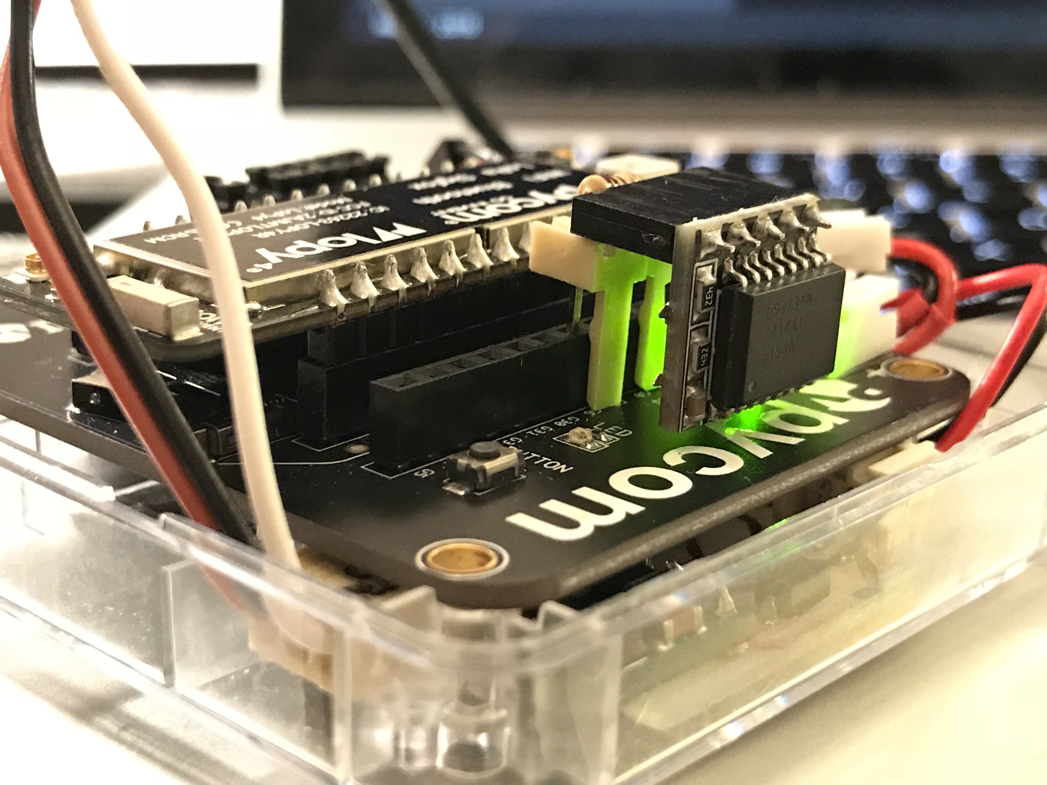 "Any two interfaces can be connected using a finite number of adapters".[/caption]
My DS3231 module comes with a battery and has 5 pins: two for power, two for I2C connectivity and one is not connected, yet it still occupies the precious place on the expansion board. I found the DS3231 MicroPython library on GitHub and was able to adapt it to Pycom board fairly easily.
RTC lagging
Once I got the external RTC up and running, I noticed that although it remembered the synced time, it stopped for around 8-10 seconds with every board reset. For the time of reset and boot-up the time wouldn't have progressed, and after that, it ran fine again, but with this several-second offset. After some investigation, I found out that LoPy4 GPIO pins connected to the power pins for DS3231 were pulled down during reset. In this case, the DS3231 activated some kind of power cut-off circuit that also switched off the onboard battery and was effectively stopping the RTC.
I solved the issue by pulling up the Vin pin of the RTC to LoPy's 3V3 output. It's not straightforward to do so on the expansion board, but this solution is good enough for a proof of concept:
[caption id="attachment_492" align="alignnone" width="2560"]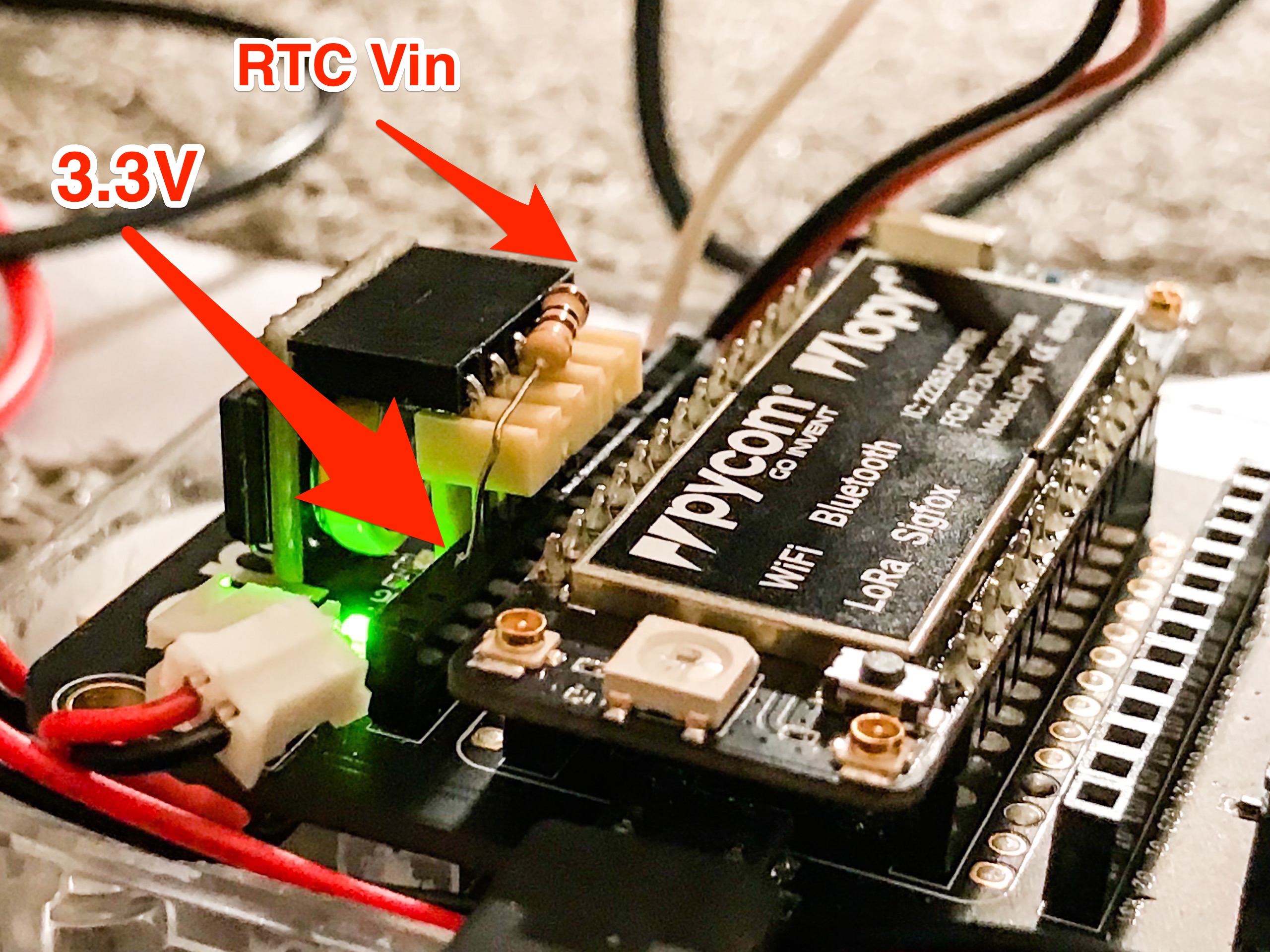 Surprise resistor![/caption]
LoRaWAN
...And then I managed to connect the board via LoRaWAN to The Things Network. It was an interesting experience, took me almost a whole weekend but now it seems to work reliably for a week already. I'll better write about it in a separate blog post though because otherwise, no-one would ever finish reading this one.
Custom PCB
[caption id="attachment_493" align="alignnone" width="1024"]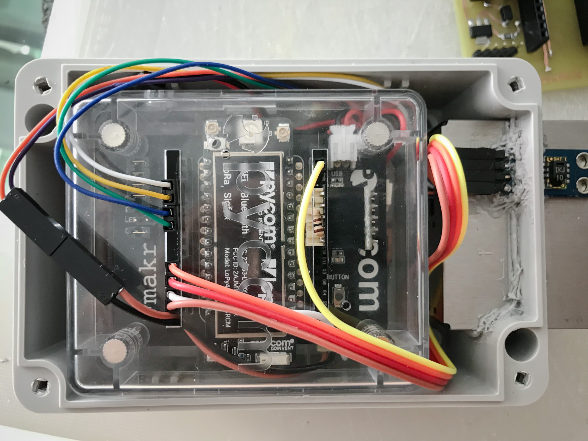 Getting tight...[/caption]
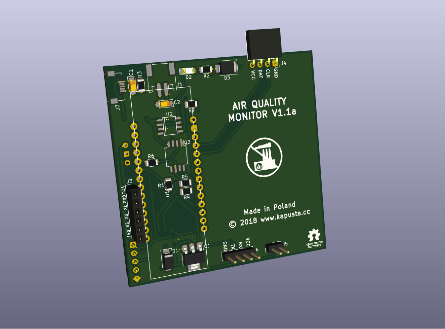
So I initially built the whole device around the expansion board and it was fine for a first prototype, with only two peripherals (the air quality sensor and the T/RH sensor). After adding the RTC, especially with an extra resistor, I thought it was too much and decided to prepare a custom circuit for the sensor.
It's not overly complicated, basically just connecting peripherals to the LoPy + a 5V power supply for the air quality monitor.
The first, home-made version of the PCB was just a proof of concept, mainly to confirm that I can get rid of the expansion board. I also decided to take things to the next level and manufacture the final boards in a PCB factory. But for now, here it is:
[caption id="attachment_495" align="alignnone" width="4032"]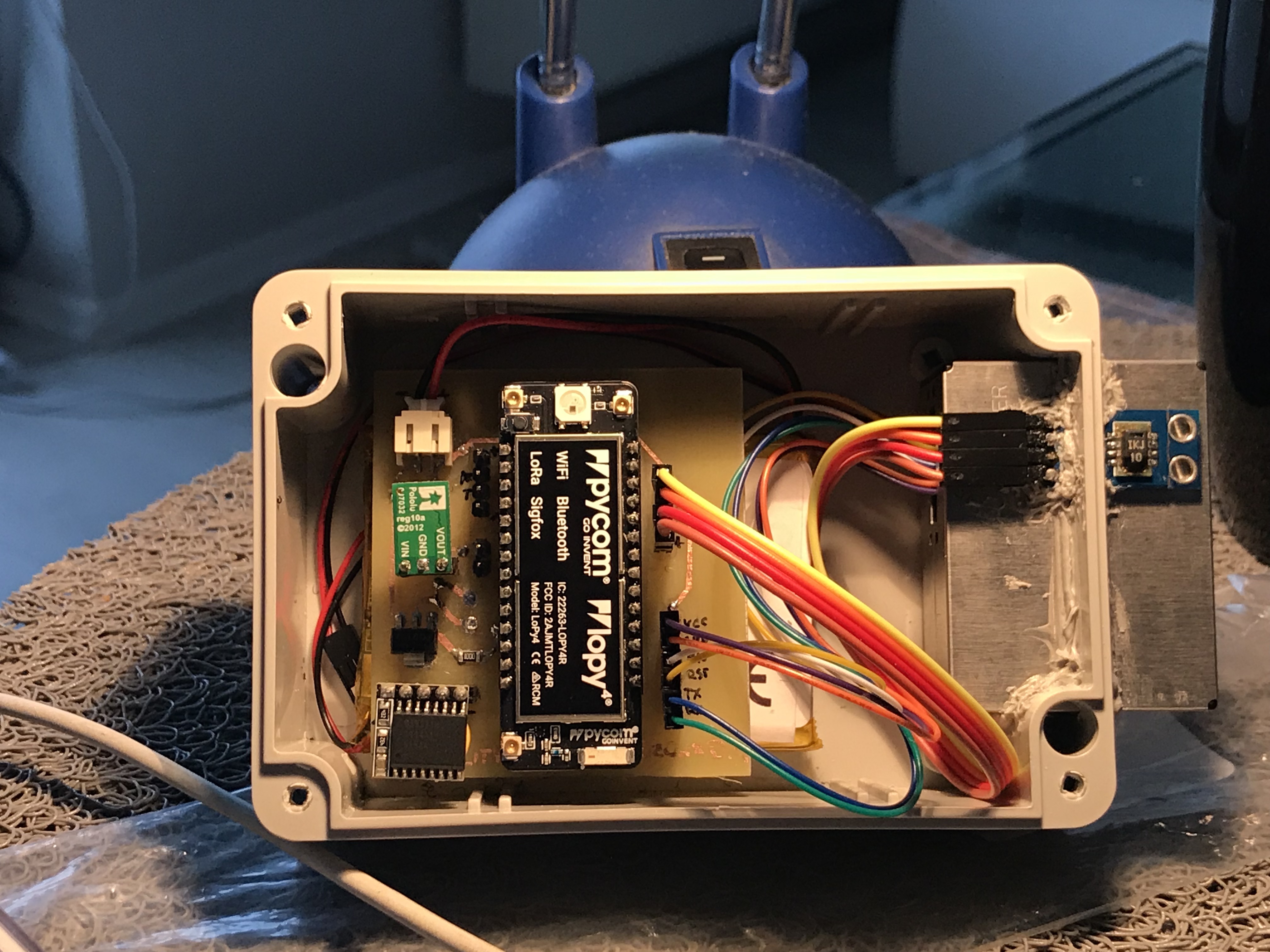 Sorry for the ugly silicone sealing![/caption]
It works great, with the exception of battery voltage measurement. Yes, I completely forgot about the voltage divider – with this board I'd need to monitor it manually with a voltmeter every couple of days...
Final PCB project
Apart from the voltage measurement circuit, the other important component missing from the board is the battery charger. I mean, for the device to be shippable and easy to use, it should come equipped with a USB port to charge the battery.
[caption id="attachment_497" align="alignnone" width="1356"] Battery charger circuit[/caption]
The battery charger circuit includes:
- the MAX1811 charger module itself,
- the micro USB port,
- the LED diode that indicates charging,
- the circuit that cuts off the battery from the load during charging, and connects the USB voltage instead. It's very cool – check out how it works over here.
This adds some significant complexity to the device and especially to the PCB layout, but I'm fine with it as I admire working with a PCB designer. As an Integrated Circuits Design graduate, I can recall a little bit the good old times of working long hours with Cadence Virtuoso, which still, compared to KiCad Pcbnew, is like building with Lego Technics vs Duplo.
The above project got sent to the factory, and while writing this, I'm still waiting for the delivery. I'll keep you posted as the PCBs arrive, hope I'll manage to solder the micro USB port correctly :)
Of course, the most up-to-date code for the device is available from Github, from the lora branch.

